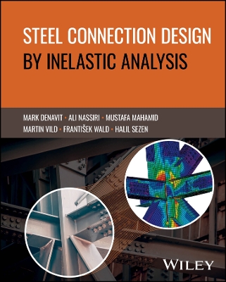
Steel Connection Design by Inelastic Analysis
 portes grátis
Steel Connection Design by Inelastic Analysis
Mahamid, Mustafa; Wald, Frantisek; Vild, Martin; Sezen, Halil; Denavit, Mark D.; Nassiri, Ali
John Wiley & Sons Inc
12/2024
384
Dura
9781394222155
Pré-lançamento - envio 15 a 20 dias após a sua edição
Descrição não disponível.
Introduction xi
1 Connection Design 1
1.1 Design Models 1
1.2 Traditional Design Methods 1
1.3 Past and Present Numerical Design Calculations 2
1.4 Validation and Verification 9
1.5 Benchmark Cases 12
1.6 Numerical Experiments 12
1.7 Experimental Validation 13
References 14
2 The Component-Based Finite Element Method 17
2.1 Material Model 17
2.2 Plate Model and Mesh Convergence 17
2.2.1 Plate Model 17
2.2.2 Mesh Convergence 19
2.3 Contacts 24
2.4 Welds 24
2.4.1 Direct Connection of Plates 24
2.4.2 Weld with Plastic Redistribution of Stress 25
2.4.3 Weld Deformation Capacity 25
2.5 Bolts 27
2.5.1 Tension 27
2.5.2 Shear 28
2.6 Interaction of Shear and Tension in a Bolt 29
2.7 High-Strength Bolts in Slip-Critical Connections 31
2.8 Anchor Bolts 32
2.8.1 Description 32
2.8.2 Anchor Bolts with Stand-Off 33
2.9 Concrete Block 33
2.9.1 Design Model 33
2.9.2 Resistance 33
2.9.3 Concrete in Compression Stiffness 34
2.10 Local Buckling of Compressed Internal Plates 35
2.11 Moment-Rotation Relation 38
2.12 Bending Stiffness 41
2.13 Deformation Capacity 43
2.14 Connection Model in Global Analyses 45
References 49
3 Welded Connection 51
3.1 Fillet Weld in a Lap Joint 51
3.1.1 Description 51
3.1.2 Analytical Model 51
3.1.3 Numerical Model 53
3.1.4 Verification of Strength 54
3.1.5 Benchmark Example 55
3.2 Fillet Weld in a Cleat Connection 57
3.2.1 Description 57
3.2.2 Investigated Cases 57
3.2.3 Verification of Strength 57
3.2.4 Benchmark Example 58
3.3 Fillet Weld of a Shear Tab 60
3.3.1 Description 60
3.3.2 Investigated Cases 60
3.3.3 Comparison of Strength 60
3.3.4 Benchmark Example 61
Reference 63
4 T-Stub Connections 65
4.1 Description 65
4.2 Slip-Critical Connections 65
4.3 Prying Action 67
4.4 Prying of the T-Stub 69
4.5 Prying of the Beam Flange 72
4.6 Summary 75
References 75
5 Beam-Over-Column Connections 77
5.1 Description 77
5.2 HSS Column Local Yielding and Crippling 78
5.3 Beam Web Local Yielding and Crippling 80
5.4 Axial Compression/Bending Moment Interaction 84
5.5 Summary 86
References 86
6 Base Plate Connections 87
6.1 Description 87
6.2 Concentric Axial Compressive Load 88
6.3 Shear Load 97
6.4 Combined Axial Compressive Load and Moment 100
6.5 Summary 102
References 103
7 Bracket Plate Connections 105
7.1 Description 105
7.2 Bolted Bracket Plate Connections 105
7.3 Bolt Shear Rupture 107
7.4 Additional Bolt Groups 108
7.5 Tearout 110
7.6 Slip Critical 111
7.7 Welded Bracket Plate Connections 111
7.8 Summary 113
References 114
8 Single Plate Shear Connections 115
8.1 Description 115
8.2 Bolt Group Strength 116
8.3 Plate Thickness 118
8.4 Other Framing Configurations 121
8.5 Location of the Point of Zero Moment 123
8.6 Stiffness Analysis 126
8.7 Summary 127
References 127
9 Extended End-Plate Moment Connections 129
9.1 Description 129
9.2 End-Plate Thickness 130
9.3 Vertical Bolt Spacing 137
9.4 Capacity Design 138
9.5 Summary 141
References 141
10 Bolted Wide Flange Splice Connections 143
10.1 Description 143
10.2 Axial Loading 144
10.3 Axial Loading with Unequal Column Depths 149
10.4 Combined Axial and Major-Axis Flexure Loading 152
10.5 Summary 154
References 154
11 Temporary Splice Connection 155
11.1 Introduction 155
11.2 Axial Load 156
11.3 Bending Moments 160
11.4 Shear Along the z-Axis 162
11.5 Shear Along the y-Axis 165
11.6 Torsion 167
11.7 Summary 168
References 169
12 Vertical Bracing Connections 171
12.1 Introduction 171
12.2 Verification Examples 172
12.3 Connection Design Capabilities of Software for HSS 175
12.4 Summary 177
References 177
13 HSS Square Braces Welded to Gusset Plates in a Concentrically Braced Frame 179
13.1 Problem Description 179
13.2 Verification of Resistance as Per AISC 179
13.3 Resistance by CBFEM 179
13.3.1 Limit States (AISC and CBFEM) 182
13.3.2 Parametric Study 195
13.4 Summary 198
Appendix 199
References 210
14 HSS Circular Braces Welded to a Gusset Plate in a Chevron Concentrically Braced Frame 211
14.1 Problem Description 211
14.2 Verification of Resistance as Per AISC 211
14.3 Resistance by CBFEM 213
14.4 Parametric Study 216
14.5 Summary 219
Appendix 220
References 229
15 Wide Flange Brace Bolted to a Gusset Plate in a Concentrically Braced Frame 231
15.1 Problem Description 231
15.2 Verification of Resistance as Per AISC 231
15.3 Verification of Resistance as Per CBFEM 231
15.4 Parametric Study 234
15.5 Summary 242
Appendix 243
References 262
16 Double Angle Brace Bolted to a Gusset Plate in a Concentrically Braced Frame 263
16.1 Problem Description 263
16.2 Verification of Resistance as Per AISC 263
16.3 Verification of Resistance as Per CBFEM 263
16.4 Resistance by CBFEM 267
16.5 Summary 273
Appendix 274
References 292
17 Double Web-Angle (DWA) Connections 293
17.1 Description 293
17.2 The Experimental Study 293
17.2.1 Instrumentation 294
17.3 Code Design Calculations and Comparisons 299
17.3.1 LRFD Design Strength Capacities of Four Test Specimens 300
17.3.2 LRFD Design Strength Capacities of Six Additional Connection Models 301
17.3.3 Calculated ASD Design Strength Capacities 302
17.4 IDEA StatiCa Analysis 303
17.5 ABAQUS Modeling and Analysis 304
17.6 Results Comparison 308
17.6.1 Comparison of IDEA StatiCa and AISC Design Strength Capacities 308
17.6.2 Comparison of IDEA StatiCa and ABAQUS Results 310
17.7 Summary 313
References 313
18 Top- and Seat-Angle with Double Web-Angle (TSADWA) Connections 315
18.1 Description 315
18.2 Experimental Study on TSADWA Connections 315
18.3 Code Design Calculations and Comparisons 317
18.3.1 Design Strength Capacity of Double Web-Angles 318
18.3.2 Design Strength Capacity of the Top- and Bottom Seat-Angles 322
18.3.3 ASD Design Strength Capacities of Test No. 14S1 324
18.4 IDEA StatiCa Analysis 324
18.4.1 Moment Capacity Analysis Using IDEA StatiCa 324
18.4.2 Moment-Rotation Analysis 327
18.5 ABAQUS Analysis 328
18.6 Results Comparison 331
18.6.1 Comparison of Connection Capacities from IDEA StatiCa Analysis, AISC Design Codes, and Experiments 331
18.6.2 Comparison of IDEA StatiCa and ABAQUS Results 332
18.7 Summary 335
References 336
19 Bolted Flange Plate (BFP) Moment Connections 337
19.1 Description 337
19.2 Experimental Study on BFP Moment Connections 337
19.3 Code Design Calculations and Comparisons 340
19.3.1 Design Strength Capacity of Single Web Plates 341
19.3.2 Design Strength Capacity of Flange Plates 343
19.3.3 Calculated ASD Design Strength Capacities of Test No. BFP 344
19.4 IDEA StatiCa Analysis 344
19.4.1 Moment Capacity Analysis Using IDEA StatiCa 344
19.4.2 Moment-Rotation Analysis 345
19.5 ABAQUS Analysis 349
19.6 Results Comparison 351
19.6.1 Comparison of IDEA StatiCa Analysis Data, AISC Design Strengths, and Test Data 351
19.6.2 Comparison of IDEA StatiCa and ABAQUS Results 353
19.7 Summary 355
References 356
20 Conclusion 357
References 358
Disclaimer 359
Terms and symbols 361
Index 363
Este título pertence ao(s) assunto(s) indicados(s). Para ver outros títulos clique no assunto desejado.
Structural steel connections; AISC 360 specifications; inelastic analysis; Component-Based Finite Element Method; CBFEM
Introduction xi
1 Connection Design 1
1.1 Design Models 1
1.2 Traditional Design Methods 1
1.3 Past and Present Numerical Design Calculations 2
1.4 Validation and Verification 9
1.5 Benchmark Cases 12
1.6 Numerical Experiments 12
1.7 Experimental Validation 13
References 14
2 The Component-Based Finite Element Method 17
2.1 Material Model 17
2.2 Plate Model and Mesh Convergence 17
2.2.1 Plate Model 17
2.2.2 Mesh Convergence 19
2.3 Contacts 24
2.4 Welds 24
2.4.1 Direct Connection of Plates 24
2.4.2 Weld with Plastic Redistribution of Stress 25
2.4.3 Weld Deformation Capacity 25
2.5 Bolts 27
2.5.1 Tension 27
2.5.2 Shear 28
2.6 Interaction of Shear and Tension in a Bolt 29
2.7 High-Strength Bolts in Slip-Critical Connections 31
2.8 Anchor Bolts 32
2.8.1 Description 32
2.8.2 Anchor Bolts with Stand-Off 33
2.9 Concrete Block 33
2.9.1 Design Model 33
2.9.2 Resistance 33
2.9.3 Concrete in Compression Stiffness 34
2.10 Local Buckling of Compressed Internal Plates 35
2.11 Moment-Rotation Relation 38
2.12 Bending Stiffness 41
2.13 Deformation Capacity 43
2.14 Connection Model in Global Analyses 45
References 49
3 Welded Connection 51
3.1 Fillet Weld in a Lap Joint 51
3.1.1 Description 51
3.1.2 Analytical Model 51
3.1.3 Numerical Model 53
3.1.4 Verification of Strength 54
3.1.5 Benchmark Example 55
3.2 Fillet Weld in a Cleat Connection 57
3.2.1 Description 57
3.2.2 Investigated Cases 57
3.2.3 Verification of Strength 57
3.2.4 Benchmark Example 58
3.3 Fillet Weld of a Shear Tab 60
3.3.1 Description 60
3.3.2 Investigated Cases 60
3.3.3 Comparison of Strength 60
3.3.4 Benchmark Example 61
Reference 63
4 T-Stub Connections 65
4.1 Description 65
4.2 Slip-Critical Connections 65
4.3 Prying Action 67
4.4 Prying of the T-Stub 69
4.5 Prying of the Beam Flange 72
4.6 Summary 75
References 75
5 Beam-Over-Column Connections 77
5.1 Description 77
5.2 HSS Column Local Yielding and Crippling 78
5.3 Beam Web Local Yielding and Crippling 80
5.4 Axial Compression/Bending Moment Interaction 84
5.5 Summary 86
References 86
6 Base Plate Connections 87
6.1 Description 87
6.2 Concentric Axial Compressive Load 88
6.3 Shear Load 97
6.4 Combined Axial Compressive Load and Moment 100
6.5 Summary 102
References 103
7 Bracket Plate Connections 105
7.1 Description 105
7.2 Bolted Bracket Plate Connections 105
7.3 Bolt Shear Rupture 107
7.4 Additional Bolt Groups 108
7.5 Tearout 110
7.6 Slip Critical 111
7.7 Welded Bracket Plate Connections 111
7.8 Summary 113
References 114
8 Single Plate Shear Connections 115
8.1 Description 115
8.2 Bolt Group Strength 116
8.3 Plate Thickness 118
8.4 Other Framing Configurations 121
8.5 Location of the Point of Zero Moment 123
8.6 Stiffness Analysis 126
8.7 Summary 127
References 127
9 Extended End-Plate Moment Connections 129
9.1 Description 129
9.2 End-Plate Thickness 130
9.3 Vertical Bolt Spacing 137
9.4 Capacity Design 138
9.5 Summary 141
References 141
10 Bolted Wide Flange Splice Connections 143
10.1 Description 143
10.2 Axial Loading 144
10.3 Axial Loading with Unequal Column Depths 149
10.4 Combined Axial and Major-Axis Flexure Loading 152
10.5 Summary 154
References 154
11 Temporary Splice Connection 155
11.1 Introduction 155
11.2 Axial Load 156
11.3 Bending Moments 160
11.4 Shear Along the z-Axis 162
11.5 Shear Along the y-Axis 165
11.6 Torsion 167
11.7 Summary 168
References 169
12 Vertical Bracing Connections 171
12.1 Introduction 171
12.2 Verification Examples 172
12.3 Connection Design Capabilities of Software for HSS 175
12.4 Summary 177
References 177
13 HSS Square Braces Welded to Gusset Plates in a Concentrically Braced Frame 179
13.1 Problem Description 179
13.2 Verification of Resistance as Per AISC 179
13.3 Resistance by CBFEM 179
13.3.1 Limit States (AISC and CBFEM) 182
13.3.2 Parametric Study 195
13.4 Summary 198
Appendix 199
References 210
14 HSS Circular Braces Welded to a Gusset Plate in a Chevron Concentrically Braced Frame 211
14.1 Problem Description 211
14.2 Verification of Resistance as Per AISC 211
14.3 Resistance by CBFEM 213
14.4 Parametric Study 216
14.5 Summary 219
Appendix 220
References 229
15 Wide Flange Brace Bolted to a Gusset Plate in a Concentrically Braced Frame 231
15.1 Problem Description 231
15.2 Verification of Resistance as Per AISC 231
15.3 Verification of Resistance as Per CBFEM 231
15.4 Parametric Study 234
15.5 Summary 242
Appendix 243
References 262
16 Double Angle Brace Bolted to a Gusset Plate in a Concentrically Braced Frame 263
16.1 Problem Description 263
16.2 Verification of Resistance as Per AISC 263
16.3 Verification of Resistance as Per CBFEM 263
16.4 Resistance by CBFEM 267
16.5 Summary 273
Appendix 274
References 292
17 Double Web-Angle (DWA) Connections 293
17.1 Description 293
17.2 The Experimental Study 293
17.2.1 Instrumentation 294
17.3 Code Design Calculations and Comparisons 299
17.3.1 LRFD Design Strength Capacities of Four Test Specimens 300
17.3.2 LRFD Design Strength Capacities of Six Additional Connection Models 301
17.3.3 Calculated ASD Design Strength Capacities 302
17.4 IDEA StatiCa Analysis 303
17.5 ABAQUS Modeling and Analysis 304
17.6 Results Comparison 308
17.6.1 Comparison of IDEA StatiCa and AISC Design Strength Capacities 308
17.6.2 Comparison of IDEA StatiCa and ABAQUS Results 310
17.7 Summary 313
References 313
18 Top- and Seat-Angle with Double Web-Angle (TSADWA) Connections 315
18.1 Description 315
18.2 Experimental Study on TSADWA Connections 315
18.3 Code Design Calculations and Comparisons 317
18.3.1 Design Strength Capacity of Double Web-Angles 318
18.3.2 Design Strength Capacity of the Top- and Bottom Seat-Angles 322
18.3.3 ASD Design Strength Capacities of Test No. 14S1 324
18.4 IDEA StatiCa Analysis 324
18.4.1 Moment Capacity Analysis Using IDEA StatiCa 324
18.4.2 Moment-Rotation Analysis 327
18.5 ABAQUS Analysis 328
18.6 Results Comparison 331
18.6.1 Comparison of Connection Capacities from IDEA StatiCa Analysis, AISC Design Codes, and Experiments 331
18.6.2 Comparison of IDEA StatiCa and ABAQUS Results 332
18.7 Summary 335
References 336
19 Bolted Flange Plate (BFP) Moment Connections 337
19.1 Description 337
19.2 Experimental Study on BFP Moment Connections 337
19.3 Code Design Calculations and Comparisons 340
19.3.1 Design Strength Capacity of Single Web Plates 341
19.3.2 Design Strength Capacity of Flange Plates 343
19.3.3 Calculated ASD Design Strength Capacities of Test No. BFP 344
19.4 IDEA StatiCa Analysis 344
19.4.1 Moment Capacity Analysis Using IDEA StatiCa 344
19.4.2 Moment-Rotation Analysis 345
19.5 ABAQUS Analysis 349
19.6 Results Comparison 351
19.6.1 Comparison of IDEA StatiCa Analysis Data, AISC Design Strengths, and Test Data 351
19.6.2 Comparison of IDEA StatiCa and ABAQUS Results 353
19.7 Summary 355
References 356
20 Conclusion 357
References 358
Disclaimer 359
Terms and symbols 361
Index 363
1 Connection Design 1
1.1 Design Models 1
1.2 Traditional Design Methods 1
1.3 Past and Present Numerical Design Calculations 2
1.4 Validation and Verification 9
1.5 Benchmark Cases 12
1.6 Numerical Experiments 12
1.7 Experimental Validation 13
References 14
2 The Component-Based Finite Element Method 17
2.1 Material Model 17
2.2 Plate Model and Mesh Convergence 17
2.2.1 Plate Model 17
2.2.2 Mesh Convergence 19
2.3 Contacts 24
2.4 Welds 24
2.4.1 Direct Connection of Plates 24
2.4.2 Weld with Plastic Redistribution of Stress 25
2.4.3 Weld Deformation Capacity 25
2.5 Bolts 27
2.5.1 Tension 27
2.5.2 Shear 28
2.6 Interaction of Shear and Tension in a Bolt 29
2.7 High-Strength Bolts in Slip-Critical Connections 31
2.8 Anchor Bolts 32
2.8.1 Description 32
2.8.2 Anchor Bolts with Stand-Off 33
2.9 Concrete Block 33
2.9.1 Design Model 33
2.9.2 Resistance 33
2.9.3 Concrete in Compression Stiffness 34
2.10 Local Buckling of Compressed Internal Plates 35
2.11 Moment-Rotation Relation 38
2.12 Bending Stiffness 41
2.13 Deformation Capacity 43
2.14 Connection Model in Global Analyses 45
References 49
3 Welded Connection 51
3.1 Fillet Weld in a Lap Joint 51
3.1.1 Description 51
3.1.2 Analytical Model 51
3.1.3 Numerical Model 53
3.1.4 Verification of Strength 54
3.1.5 Benchmark Example 55
3.2 Fillet Weld in a Cleat Connection 57
3.2.1 Description 57
3.2.2 Investigated Cases 57
3.2.3 Verification of Strength 57
3.2.4 Benchmark Example 58
3.3 Fillet Weld of a Shear Tab 60
3.3.1 Description 60
3.3.2 Investigated Cases 60
3.3.3 Comparison of Strength 60
3.3.4 Benchmark Example 61
Reference 63
4 T-Stub Connections 65
4.1 Description 65
4.2 Slip-Critical Connections 65
4.3 Prying Action 67
4.4 Prying of the T-Stub 69
4.5 Prying of the Beam Flange 72
4.6 Summary 75
References 75
5 Beam-Over-Column Connections 77
5.1 Description 77
5.2 HSS Column Local Yielding and Crippling 78
5.3 Beam Web Local Yielding and Crippling 80
5.4 Axial Compression/Bending Moment Interaction 84
5.5 Summary 86
References 86
6 Base Plate Connections 87
6.1 Description 87
6.2 Concentric Axial Compressive Load 88
6.3 Shear Load 97
6.4 Combined Axial Compressive Load and Moment 100
6.5 Summary 102
References 103
7 Bracket Plate Connections 105
7.1 Description 105
7.2 Bolted Bracket Plate Connections 105
7.3 Bolt Shear Rupture 107
7.4 Additional Bolt Groups 108
7.5 Tearout 110
7.6 Slip Critical 111
7.7 Welded Bracket Plate Connections 111
7.8 Summary 113
References 114
8 Single Plate Shear Connections 115
8.1 Description 115
8.2 Bolt Group Strength 116
8.3 Plate Thickness 118
8.4 Other Framing Configurations 121
8.5 Location of the Point of Zero Moment 123
8.6 Stiffness Analysis 126
8.7 Summary 127
References 127
9 Extended End-Plate Moment Connections 129
9.1 Description 129
9.2 End-Plate Thickness 130
9.3 Vertical Bolt Spacing 137
9.4 Capacity Design 138
9.5 Summary 141
References 141
10 Bolted Wide Flange Splice Connections 143
10.1 Description 143
10.2 Axial Loading 144
10.3 Axial Loading with Unequal Column Depths 149
10.4 Combined Axial and Major-Axis Flexure Loading 152
10.5 Summary 154
References 154
11 Temporary Splice Connection 155
11.1 Introduction 155
11.2 Axial Load 156
11.3 Bending Moments 160
11.4 Shear Along the z-Axis 162
11.5 Shear Along the y-Axis 165
11.6 Torsion 167
11.7 Summary 168
References 169
12 Vertical Bracing Connections 171
12.1 Introduction 171
12.2 Verification Examples 172
12.3 Connection Design Capabilities of Software for HSS 175
12.4 Summary 177
References 177
13 HSS Square Braces Welded to Gusset Plates in a Concentrically Braced Frame 179
13.1 Problem Description 179
13.2 Verification of Resistance as Per AISC 179
13.3 Resistance by CBFEM 179
13.3.1 Limit States (AISC and CBFEM) 182
13.3.2 Parametric Study 195
13.4 Summary 198
Appendix 199
References 210
14 HSS Circular Braces Welded to a Gusset Plate in a Chevron Concentrically Braced Frame 211
14.1 Problem Description 211
14.2 Verification of Resistance as Per AISC 211
14.3 Resistance by CBFEM 213
14.4 Parametric Study 216
14.5 Summary 219
Appendix 220
References 229
15 Wide Flange Brace Bolted to a Gusset Plate in a Concentrically Braced Frame 231
15.1 Problem Description 231
15.2 Verification of Resistance as Per AISC 231
15.3 Verification of Resistance as Per CBFEM 231
15.4 Parametric Study 234
15.5 Summary 242
Appendix 243
References 262
16 Double Angle Brace Bolted to a Gusset Plate in a Concentrically Braced Frame 263
16.1 Problem Description 263
16.2 Verification of Resistance as Per AISC 263
16.3 Verification of Resistance as Per CBFEM 263
16.4 Resistance by CBFEM 267
16.5 Summary 273
Appendix 274
References 292
17 Double Web-Angle (DWA) Connections 293
17.1 Description 293
17.2 The Experimental Study 293
17.2.1 Instrumentation 294
17.3 Code Design Calculations and Comparisons 299
17.3.1 LRFD Design Strength Capacities of Four Test Specimens 300
17.3.2 LRFD Design Strength Capacities of Six Additional Connection Models 301
17.3.3 Calculated ASD Design Strength Capacities 302
17.4 IDEA StatiCa Analysis 303
17.5 ABAQUS Modeling and Analysis 304
17.6 Results Comparison 308
17.6.1 Comparison of IDEA StatiCa and AISC Design Strength Capacities 308
17.6.2 Comparison of IDEA StatiCa and ABAQUS Results 310
17.7 Summary 313
References 313
18 Top- and Seat-Angle with Double Web-Angle (TSADWA) Connections 315
18.1 Description 315
18.2 Experimental Study on TSADWA Connections 315
18.3 Code Design Calculations and Comparisons 317
18.3.1 Design Strength Capacity of Double Web-Angles 318
18.3.2 Design Strength Capacity of the Top- and Bottom Seat-Angles 322
18.3.3 ASD Design Strength Capacities of Test No. 14S1 324
18.4 IDEA StatiCa Analysis 324
18.4.1 Moment Capacity Analysis Using IDEA StatiCa 324
18.4.2 Moment-Rotation Analysis 327
18.5 ABAQUS Analysis 328
18.6 Results Comparison 331
18.6.1 Comparison of Connection Capacities from IDEA StatiCa Analysis, AISC Design Codes, and Experiments 331
18.6.2 Comparison of IDEA StatiCa and ABAQUS Results 332
18.7 Summary 335
References 336
19 Bolted Flange Plate (BFP) Moment Connections 337
19.1 Description 337
19.2 Experimental Study on BFP Moment Connections 337
19.3 Code Design Calculations and Comparisons 340
19.3.1 Design Strength Capacity of Single Web Plates 341
19.3.2 Design Strength Capacity of Flange Plates 343
19.3.3 Calculated ASD Design Strength Capacities of Test No. BFP 344
19.4 IDEA StatiCa Analysis 344
19.4.1 Moment Capacity Analysis Using IDEA StatiCa 344
19.4.2 Moment-Rotation Analysis 345
19.5 ABAQUS Analysis 349
19.6 Results Comparison 351
19.6.1 Comparison of IDEA StatiCa Analysis Data, AISC Design Strengths, and Test Data 351
19.6.2 Comparison of IDEA StatiCa and ABAQUS Results 353
19.7 Summary 355
References 356
20 Conclusion 357
References 358
Disclaimer 359
Terms and symbols 361
Index 363
Este título pertence ao(s) assunto(s) indicados(s). Para ver outros títulos clique no assunto desejado.

